New Interface for Musical Expression on a piece of wood
This project combines a classic sound making device with an even older, but rarely used, circuit building technique
This isn't really a new interface - Forrest M. Mims III first published in 1980 a circuit for what he called a "Stepped Tone Generator". It is now commonly known as an Atari Punk Console because it sounds like the early video games of the 80s and has developed a bit of a cult following.
In the original design the device was controlled by two potentiometers. A common modification is to replace these with two photoresistors, allowing it to be controlled by blocking the light to these sensors, giving it a bit of a Theremin-like feel. Flashing lights can add an interesting effect, and there are endless ways to build and modify this device.
In this workshop we will construct the circuit on a piece of wood, using small nails as the tie points and using point-to-point wiring. (Using a piece of wood on which to build a circuit is what gives as the term breadboarding.). The wood can be of any shape, and the circuit can be laid out in almost any way, encouraging a great deal of creativity.
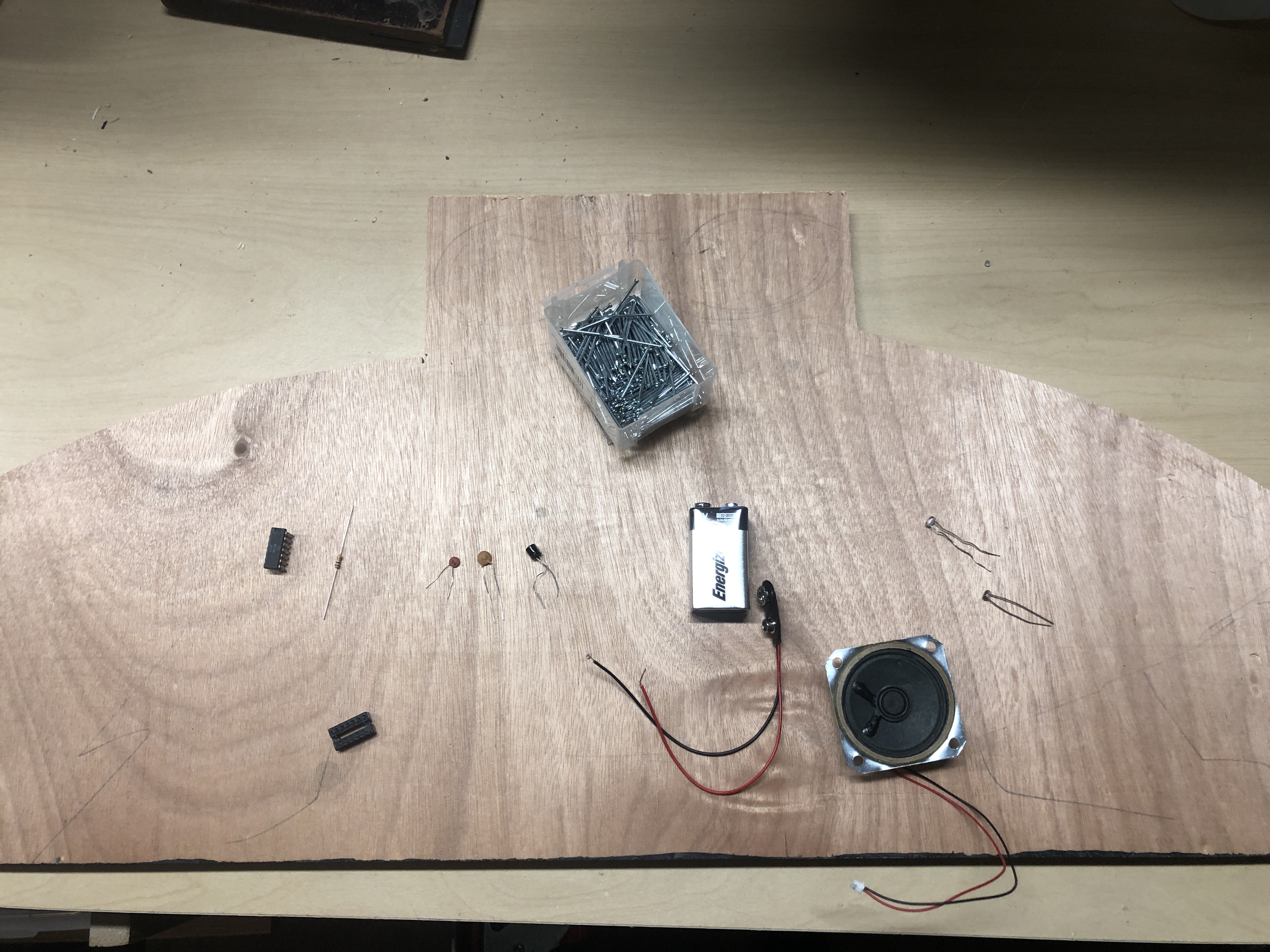
Parts
Unless otherwise indicated, one of each is required.
- 556 dual timer IC such as this
- 1K resistor such as this
- Light dependent resistor such as this (quantity: 2)
- .01 uF ceramic disc capacitor such as this
- .1 uF capacitor such as this
- 10 uF capacitor such as this
- 9V battery
- 9V battery clip such as this
- 8 ohm speaker such as this
- 14 pin IC socket such as this
- 14 pin DIP breakout board (optional)
- Piece of wood, about 12" x 12", weird arbitrary shape preferred. Can be plywood or solid wood, but not a hard material such as MDF as it's difficult to hammer nails into the hard wood
Parts for Modifications
A long standing tradition among electrical and electronic experimenters is to modify circuits. For this purpose the following components can be used in addition to, or to replace, some of the key components in this project to change the behavior of the circuit.
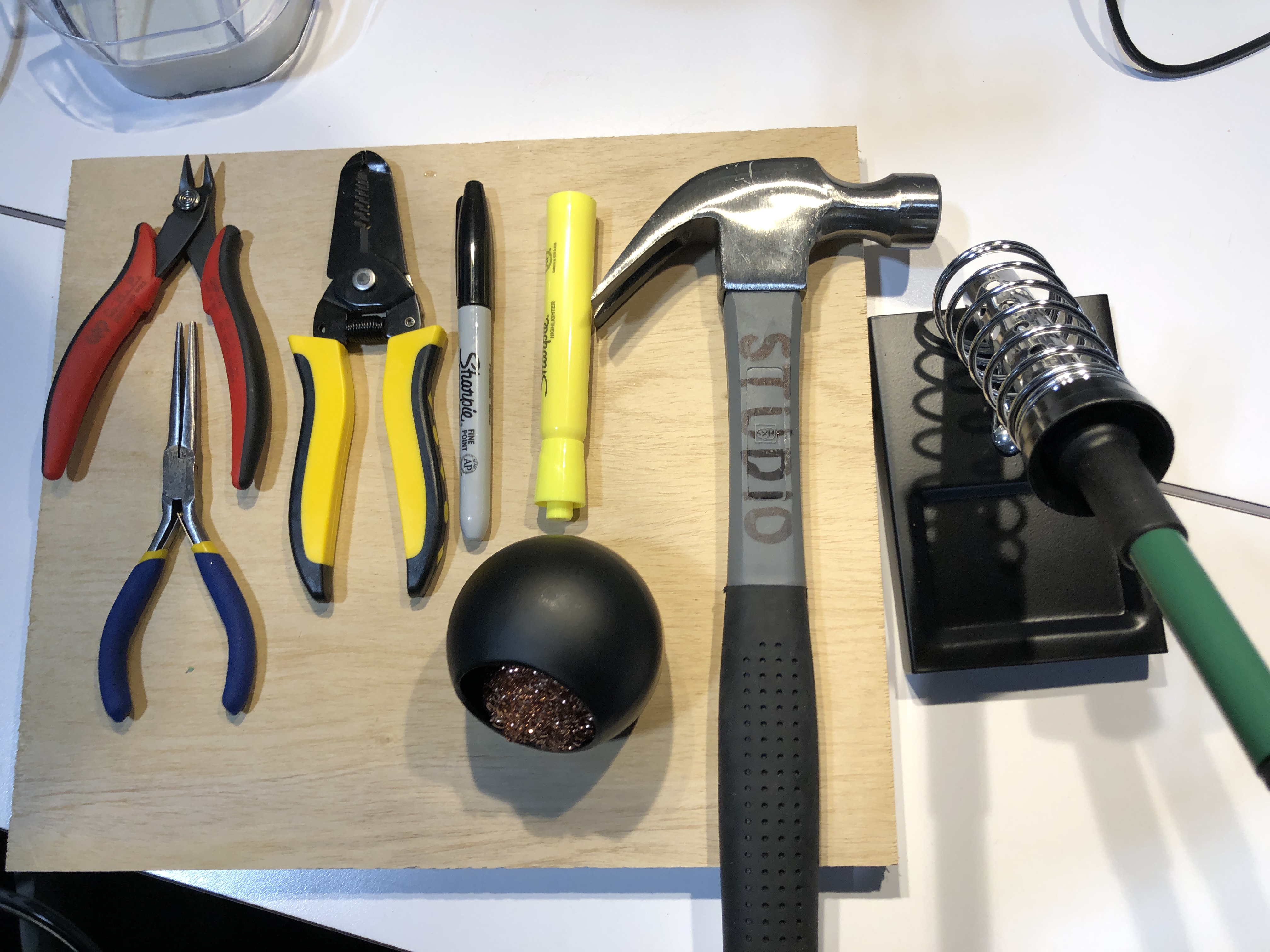
Tools
One set of tools per 5 participants or so
- Hammer
- Temperature controlled soldering iron such as this
- Soldering iron holder and tip cleaner such as this
- Small wire cutters
- Wire strippers such as this set which contains both a wire cutter and wire stripper
- Needle nose pliers such as this set which contains two small needle nose pliers
- Black Sharpie
- Highlight pen (any color)
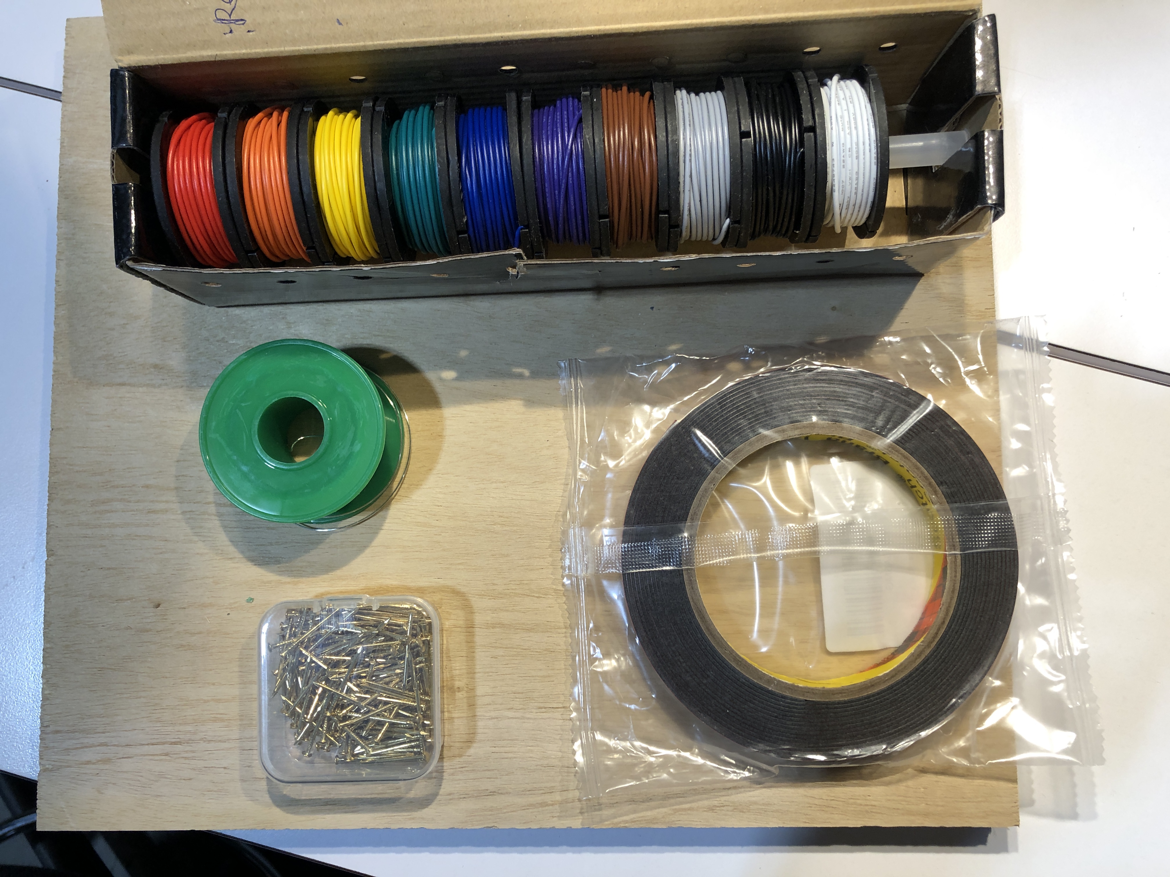
Supplies
- Solid core wire, 22 AWG, assorted colors such as this. Each project requires about 3'.
- Solder such as this
- Small nails or brads, about 18 gauge, about 1" long, such as this or this. Avoid stainless as it is difficult to solder. Brass plated is much better. Each project requires about 30 nails.
- Hot glue, double sided tape, or self stick Velcro such as this. Each project requires about 4".

Planning the Layout
Decide roughly where you want to place the components. You may be inspired by the shape of your piece of wood, or not.
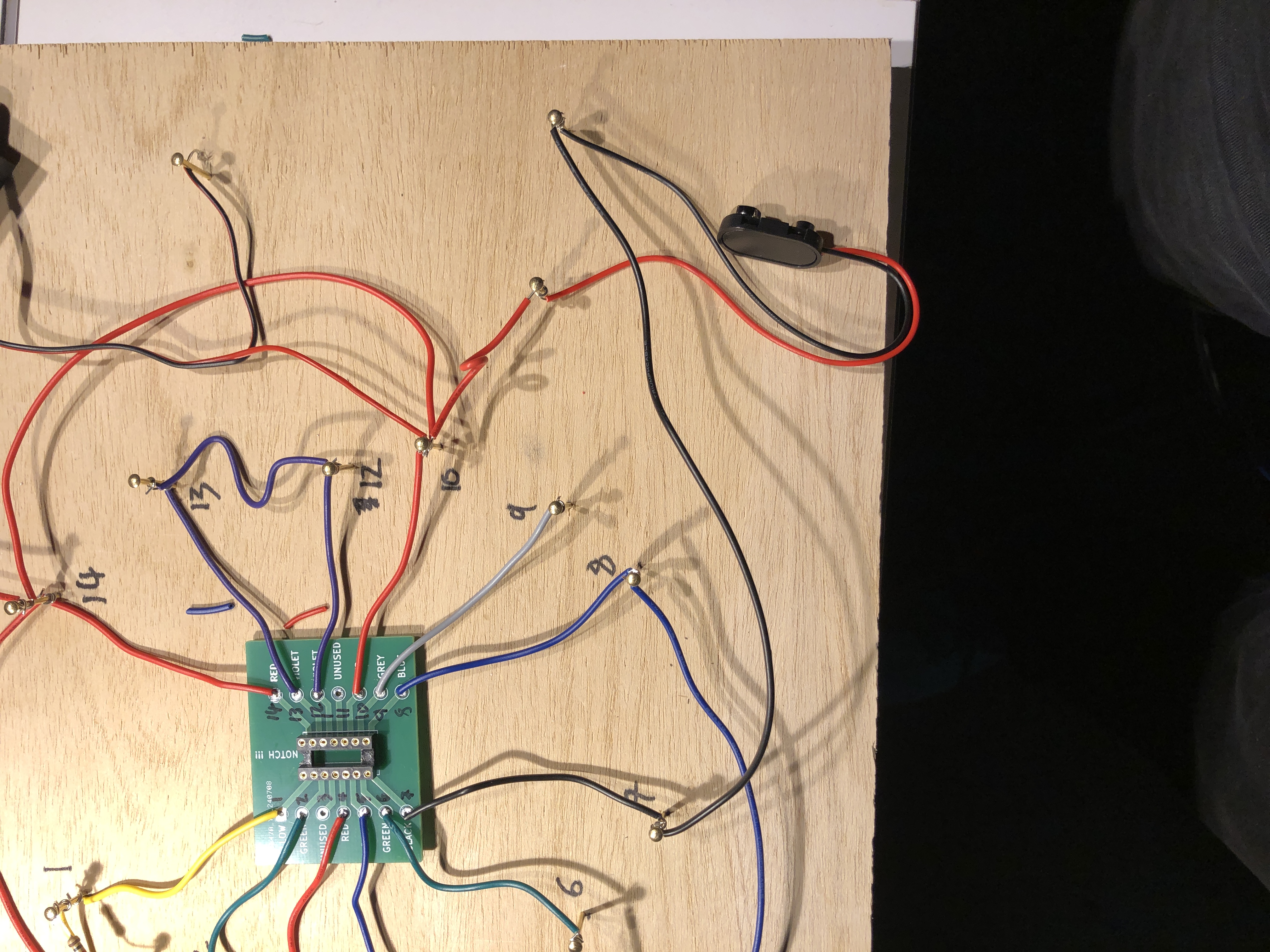
The important components are the battery, loud speaker, the 556 Dual Timer Integrated Circuit (IC) which will be mounted on a green breakout board, and the two photoresistors which will be the controls of your device.
Many wires will be attached to the green breakout board, so place it in a position that has a lot of empty space around it. Around the center is probably the best place for this.
Be creative! Use your imagination! Don't worry about being precise. You can make changes as you go along.
Use the Sharpie if you wish to mark where you want to put components.
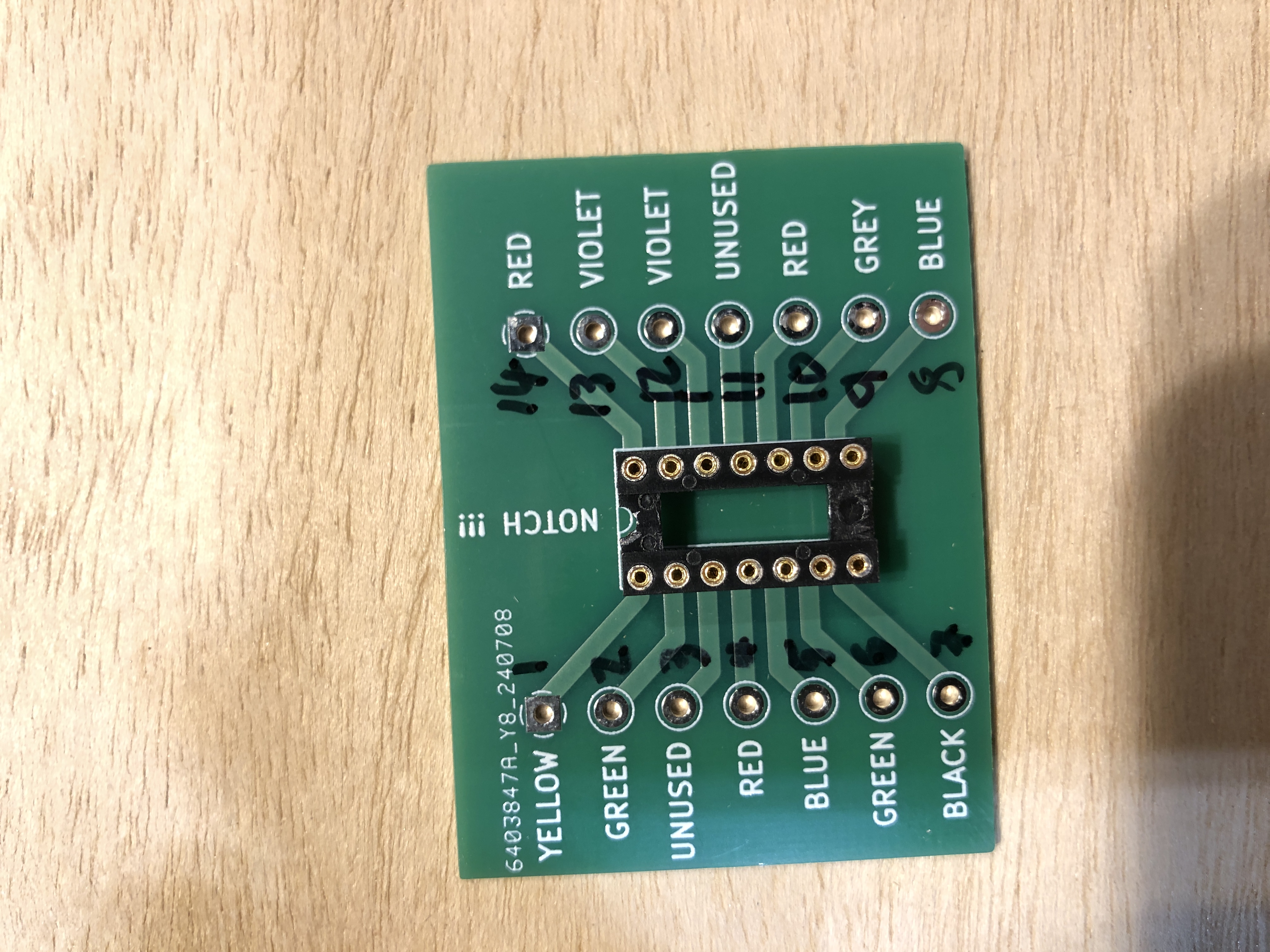
Solder the IC socket to the breakout board
Pay attention to the orientation. The socket has a notch on one end. Make sure this aligns with the notch on the breakout board.
The socket goes on the top side of the board, which is the side with the white writing.
If by accident you solder two pins together, call me over and I'll help you fix that
Soldering Wires to the Breakout Board
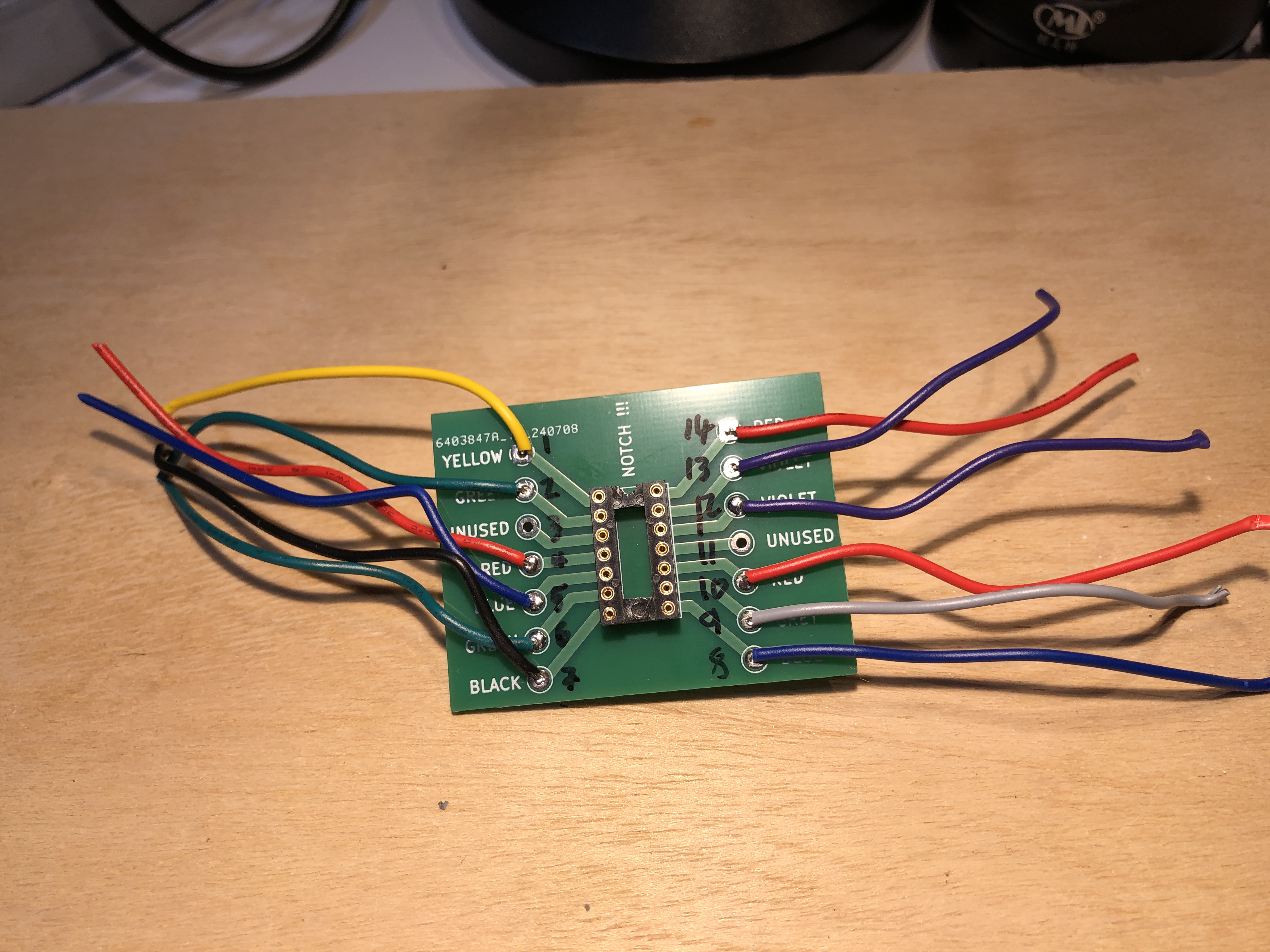
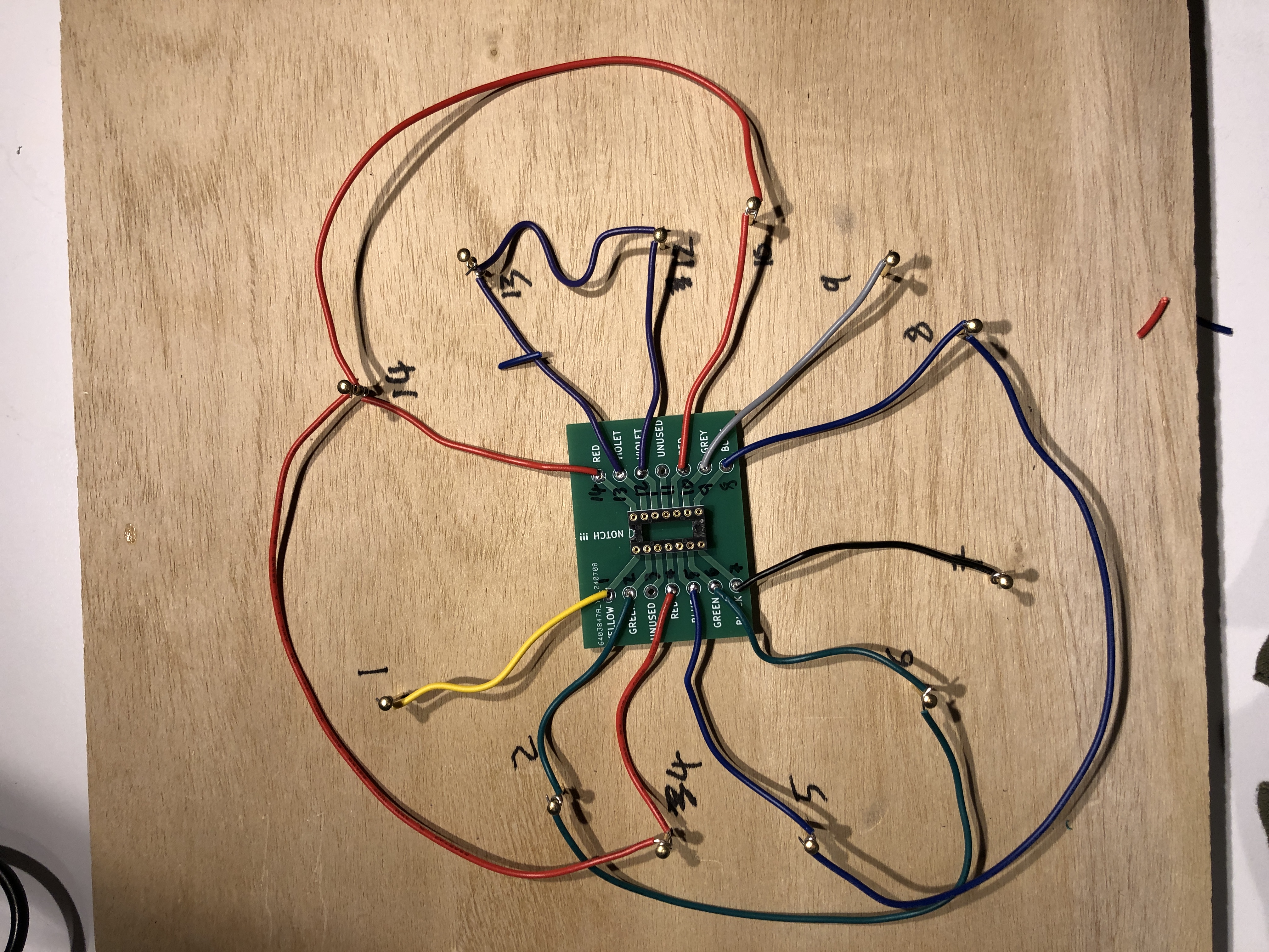
Solder wires to the breakout board.
First prepare cut wires about 3-4" long.
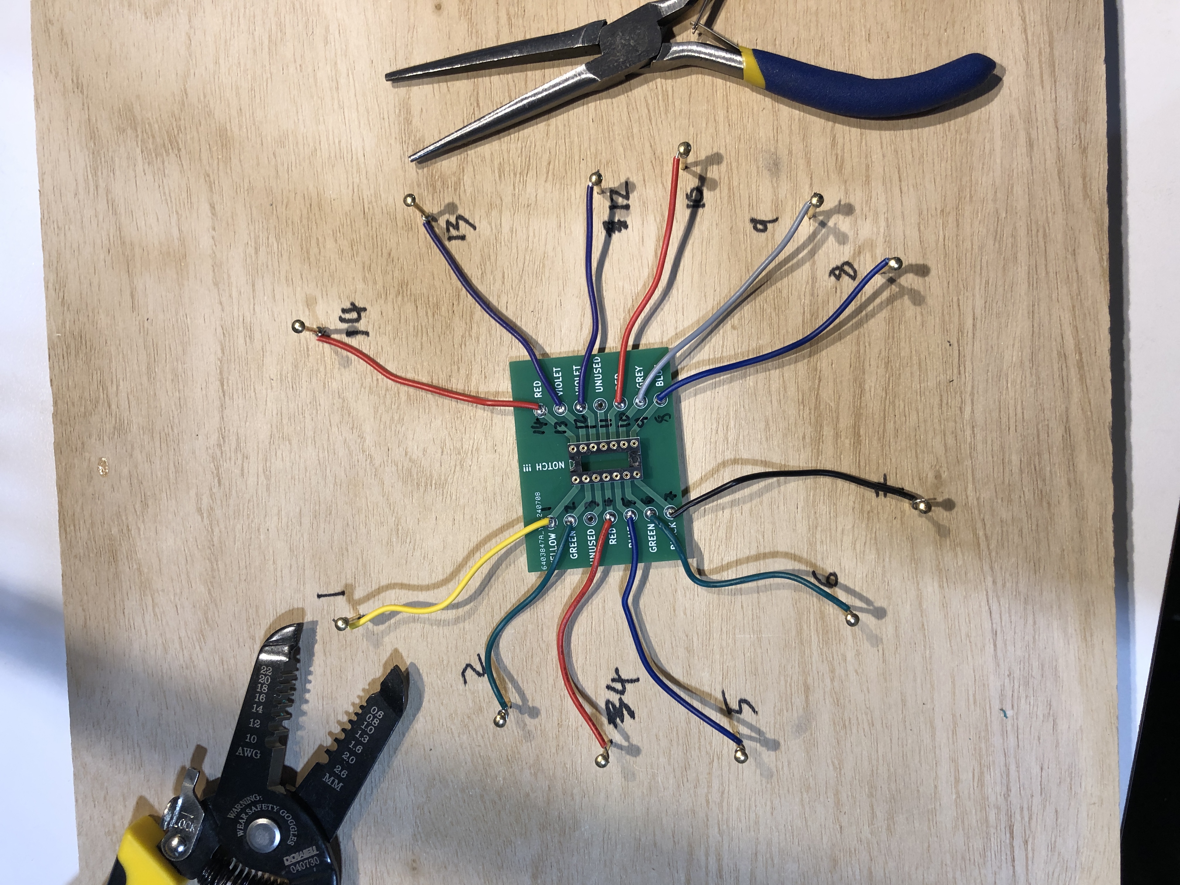
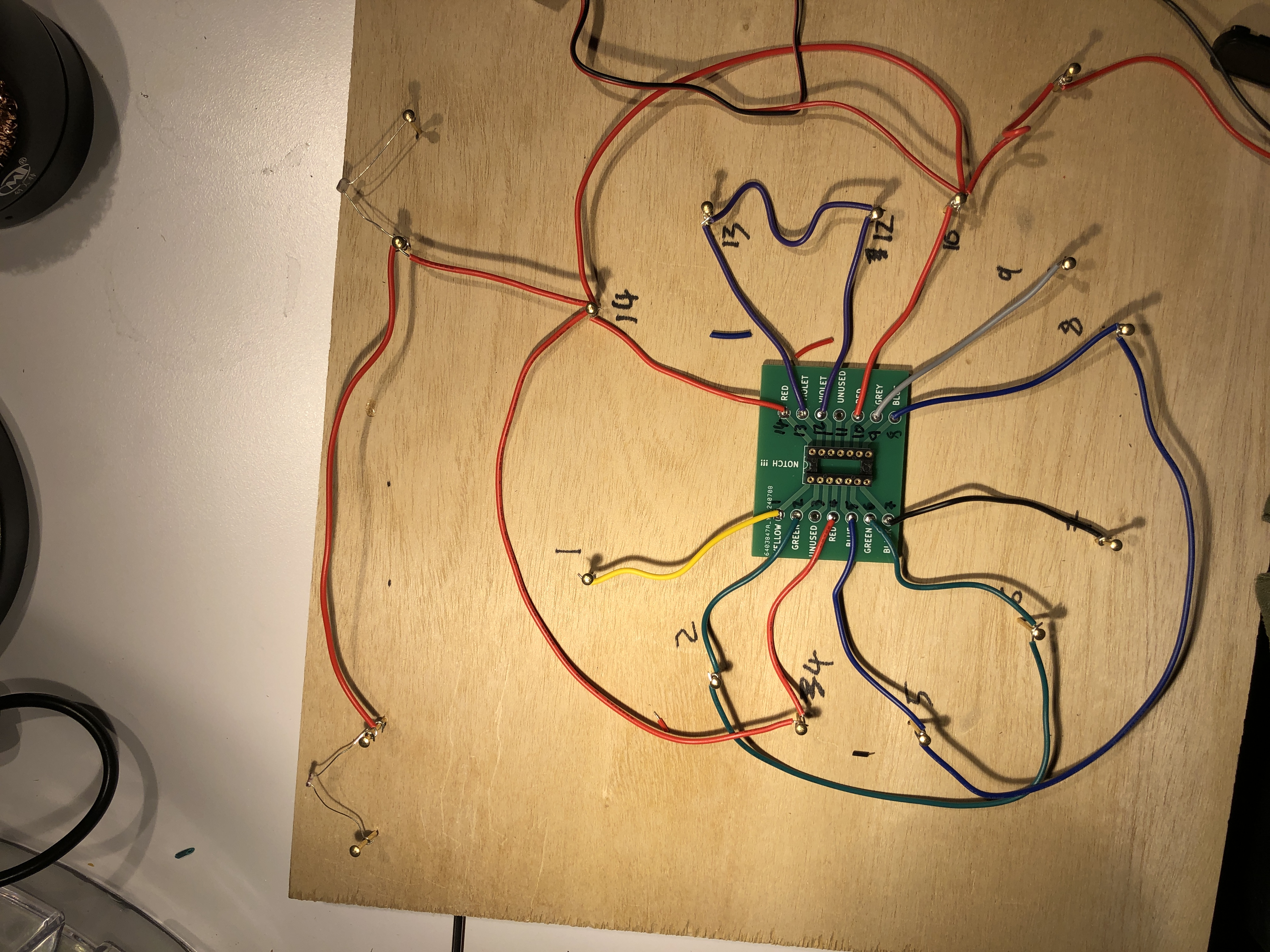
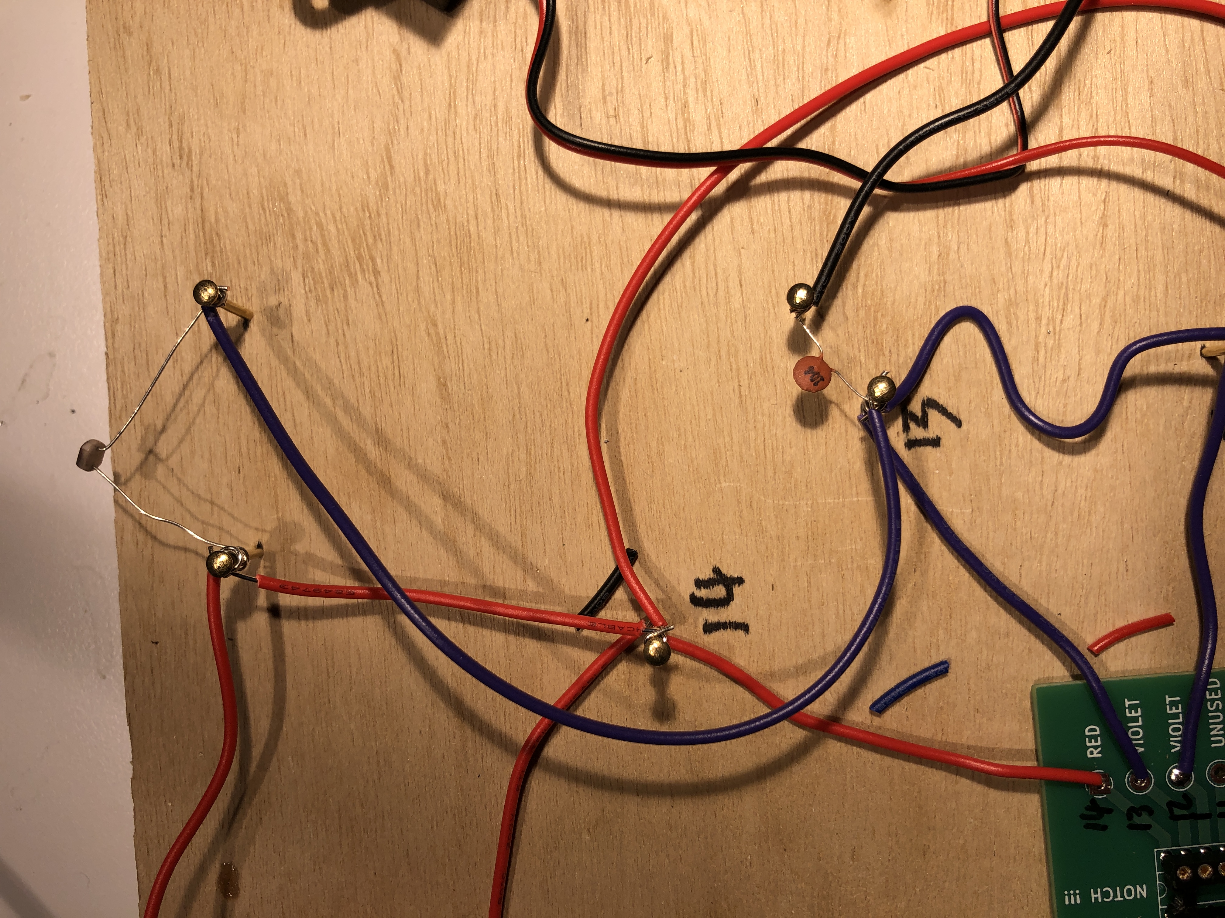
Strip about 1/4" off one end of each wire and insert it into the correct hole on the breakout board. Make sure to use the correct colors. Note that the violet and blue wires look similar.
Once you have verified the correct color, solder the wire into the breakout board Note that some holes are unused.
Note that the holes are numbered starting at the top left, down on the left, then up on the right.
When you have finished soldering, trim any excess wire from the back of the board
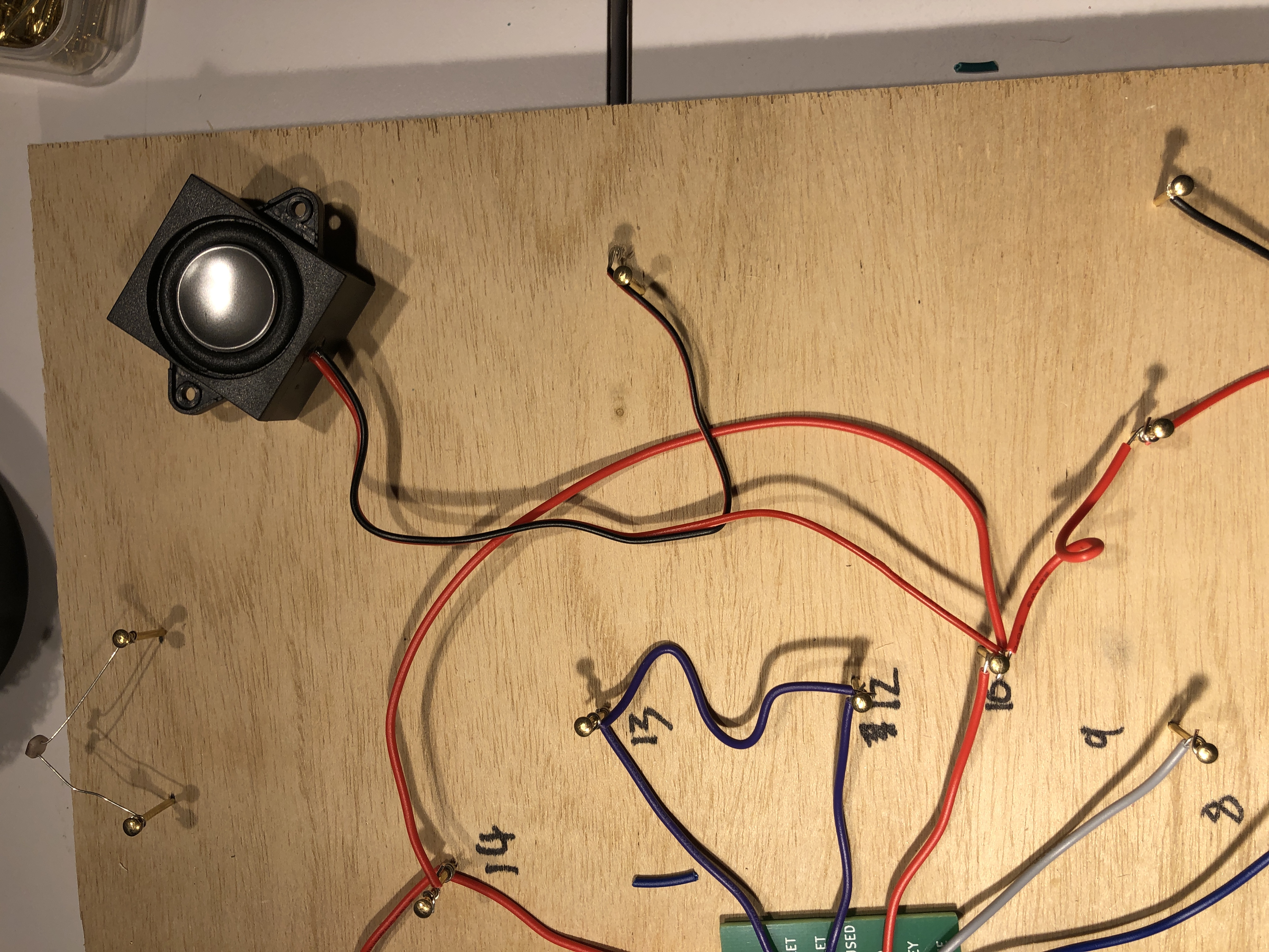
- Red: pins 4, 10, and 14
- Yellow: pin 1
- Green: pins 2, 6
- Blue: pins 5, 8
- Violet: pins 12, 13
- Grey: pin 9
- Black: pin 7
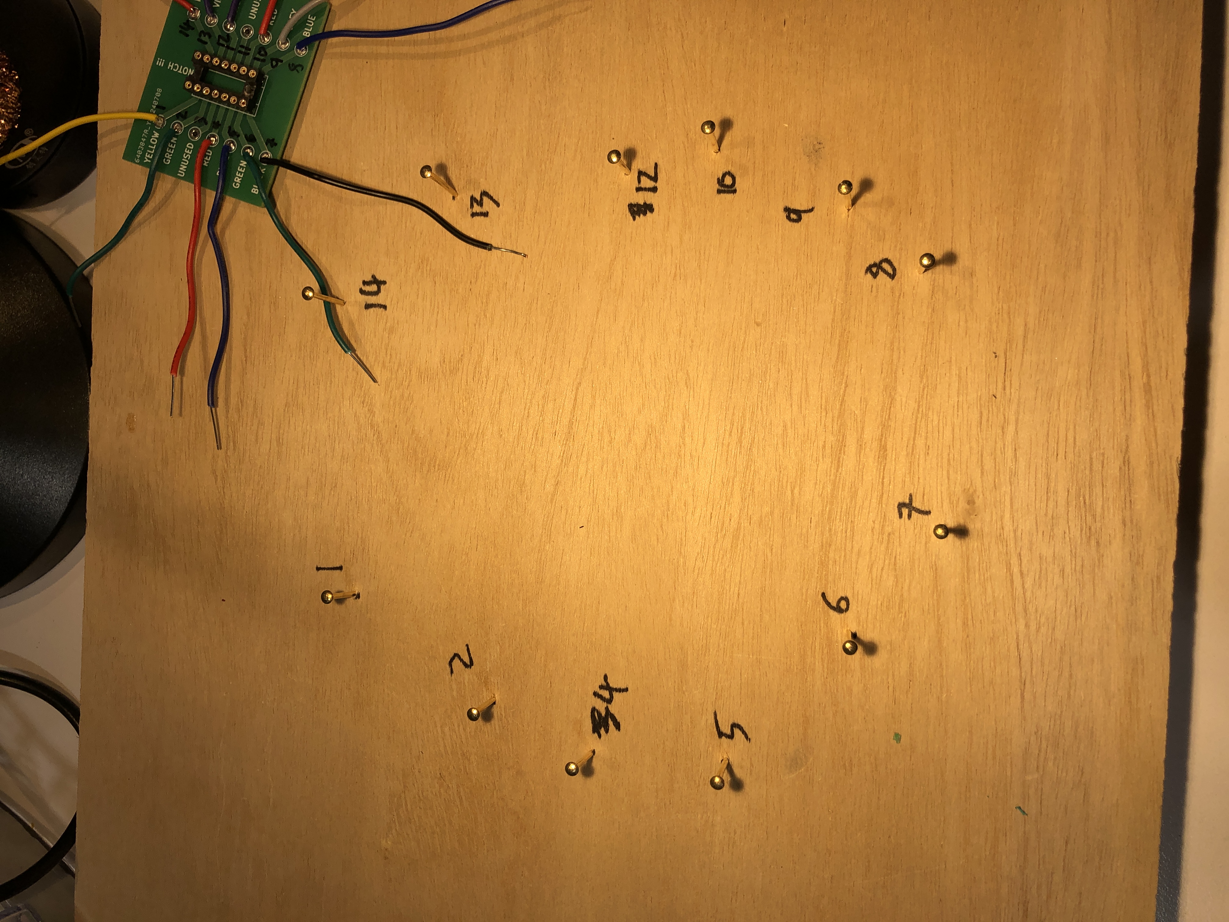
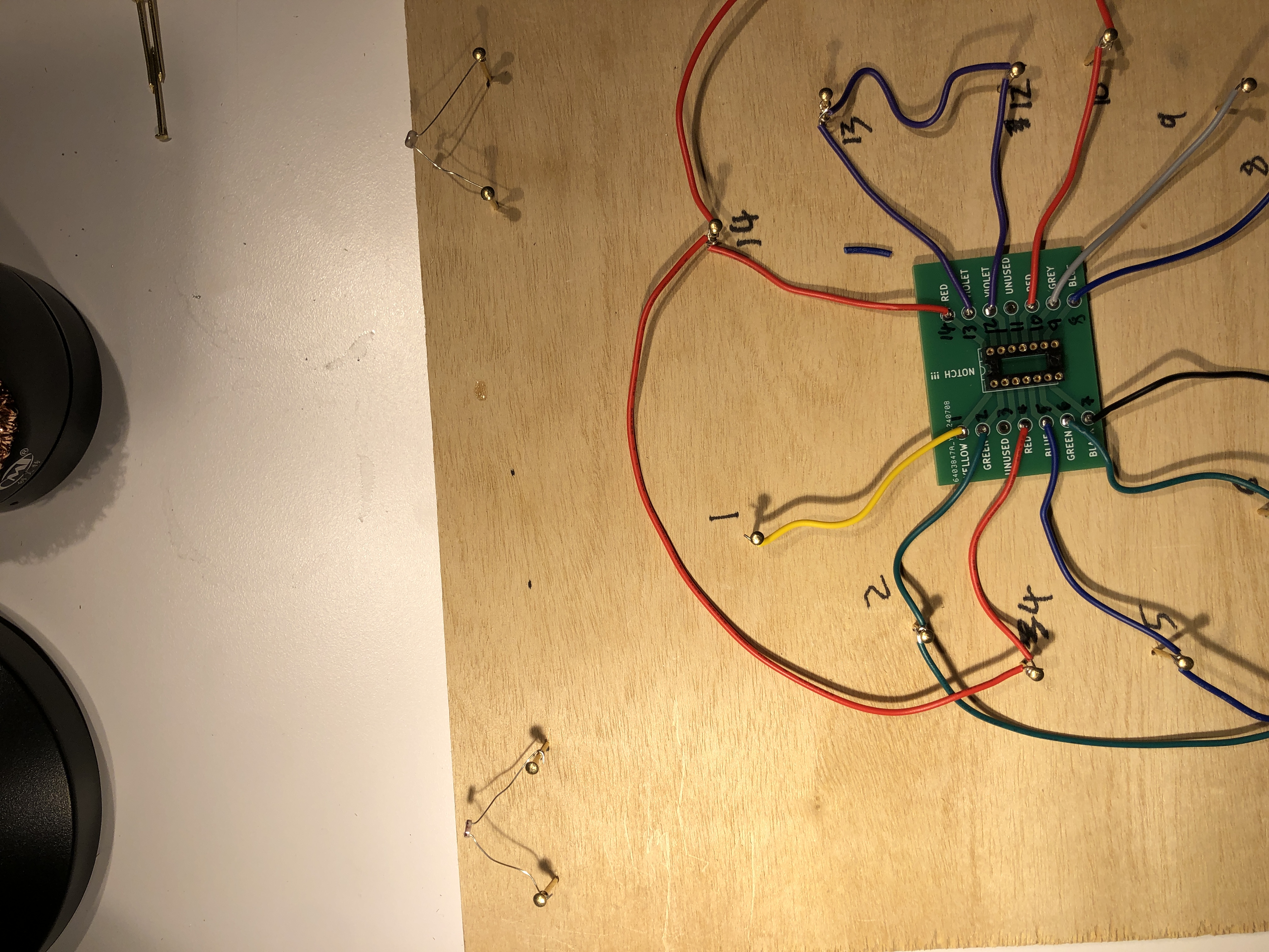
Plan Where To Put the Nails For The IC
Spread out the wires as much as possible, and strip about 1/2" from each wire.
Mark with a Sharpie where you want to put the nails for the wires coming from the dual timer IC. Put the mark no further than where the stripped part starts, because you will need to wrap this part of the wire around the nail. You can even go a little closer to the breakout board.
Write down the pin numbers. This will help avoid mistakes later on. Remember to skip the numbers 3 and 11.
Note that the holes are numbered starting at the top left, down on the left, then up on the right.
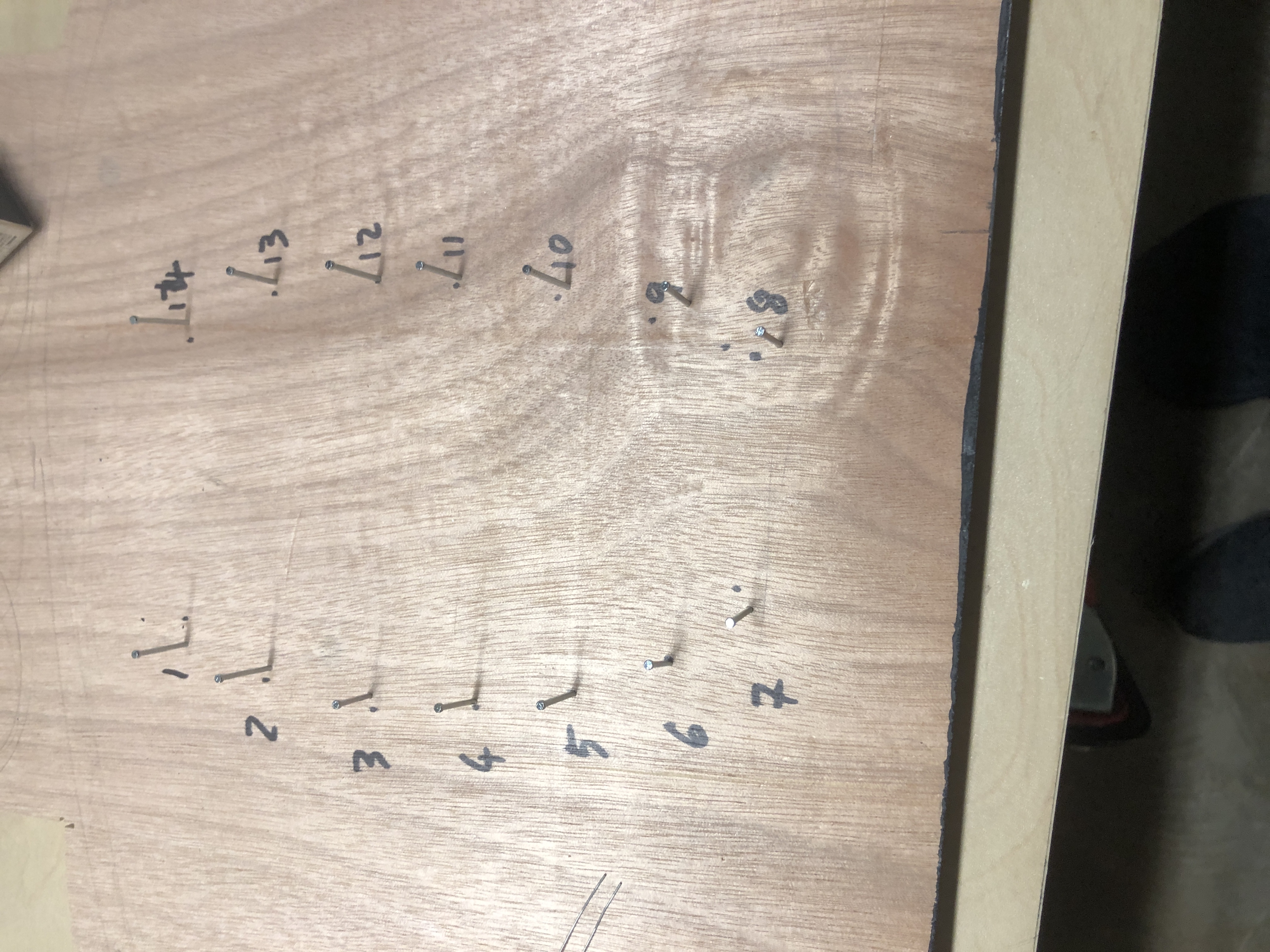
Add the Nails for the Dual Timer IC
Move the breakout board aside and hammer in the nails, only as far as needed to make the nail stable. You must leave at least half the nail out.
Wrap the Stripped Wires Around the Nails
Wrap only the stripped part around the nail. You must wrap tightly, so use the pliers or the tips of the wire cutters to help if necessary.
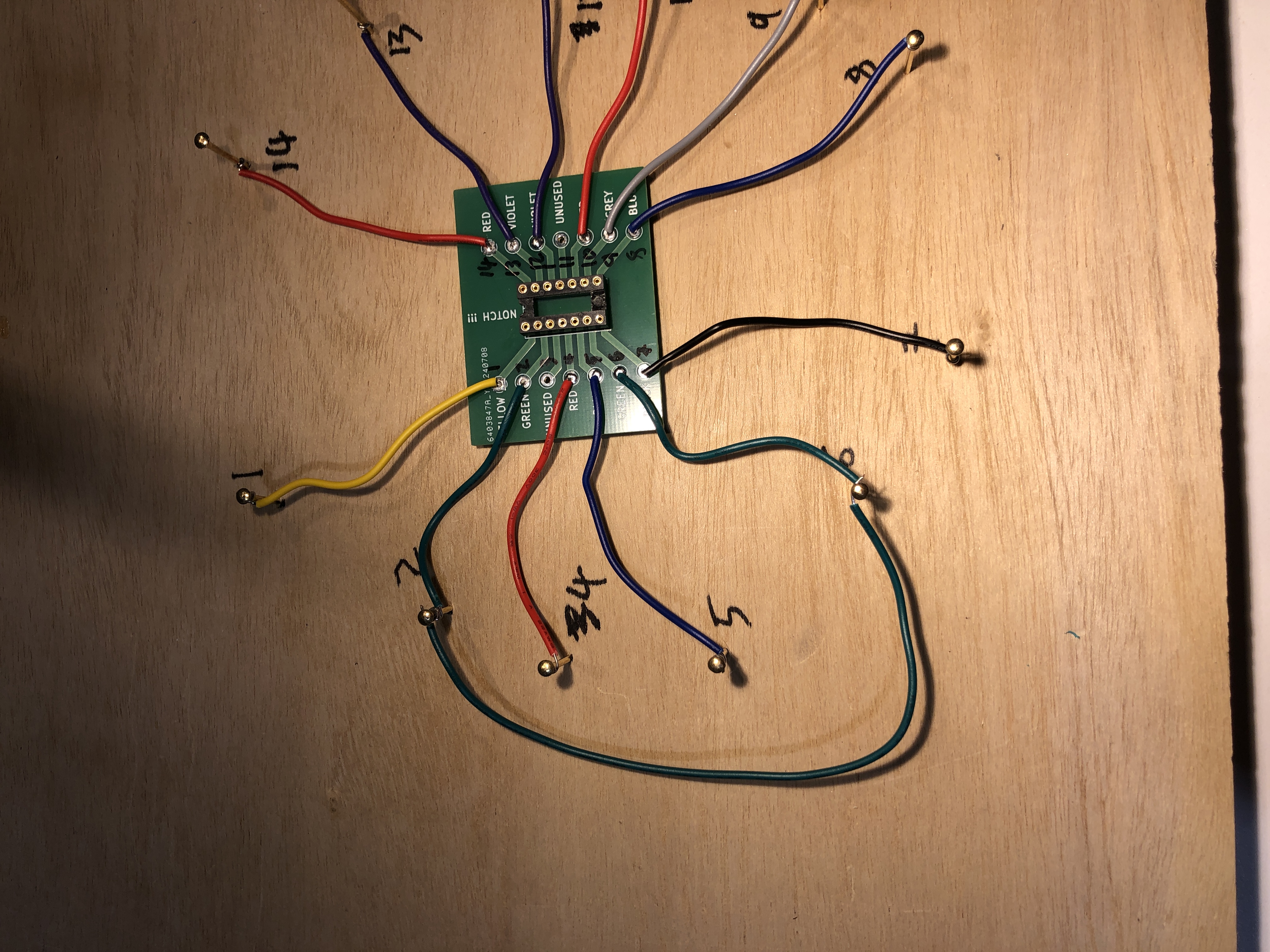
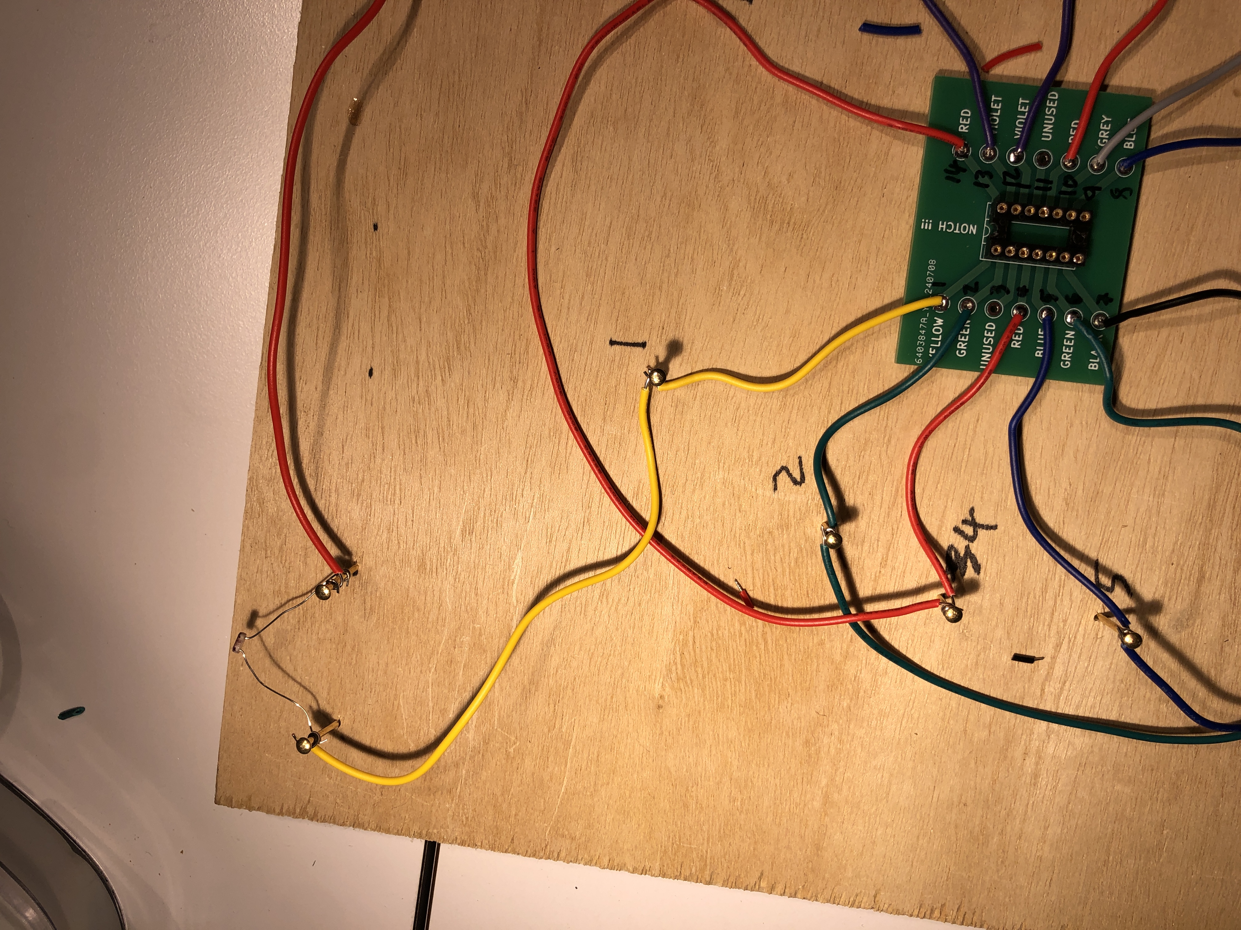
Connect Pins 2 and 6 with a Green Wire
As always, make sure to use the correct color. As always, don't make the wire too short. Strip the wire about 1/2" and wrap it tightly around the nails.
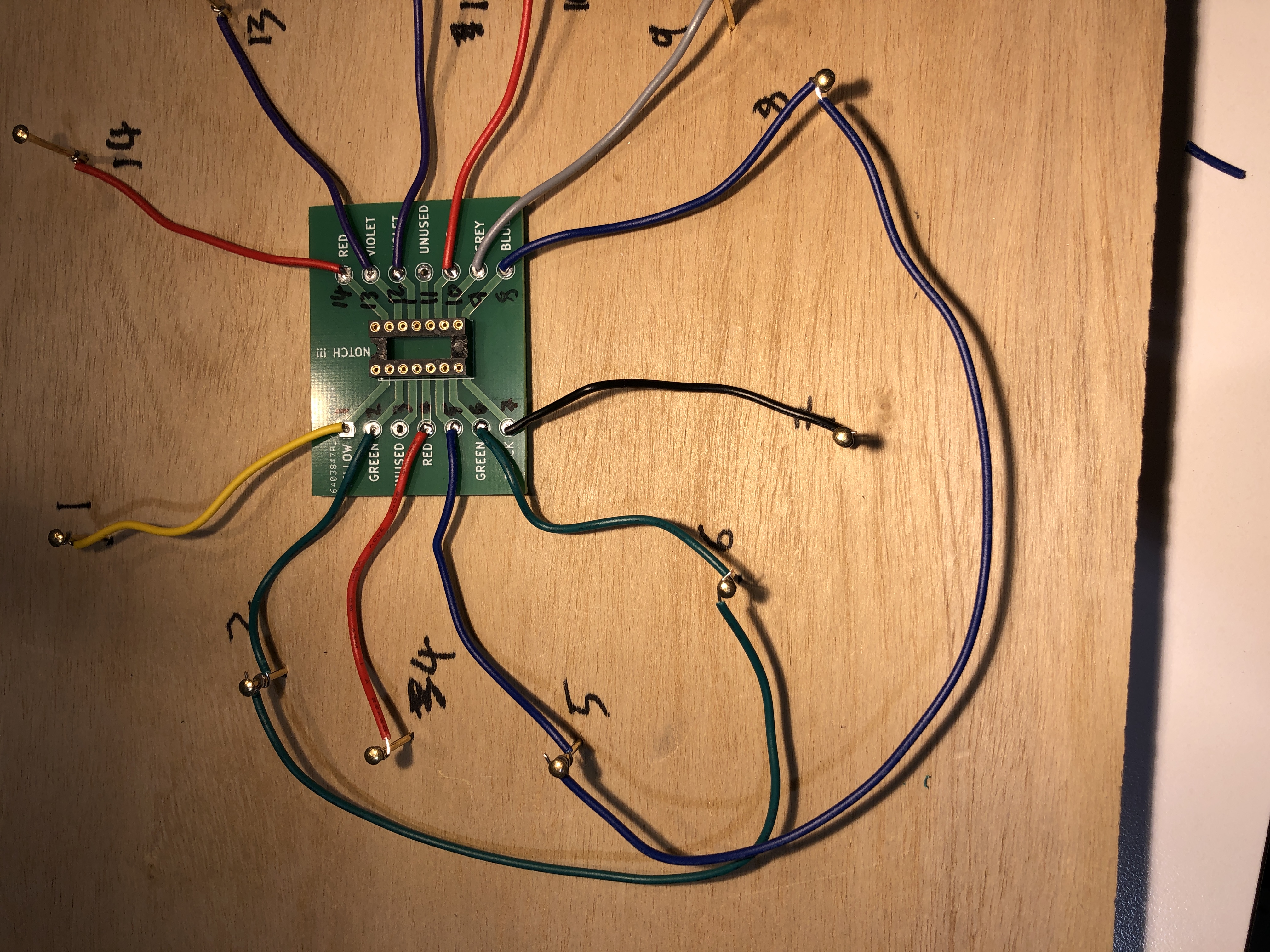
Connect Pins 5 and 8 with a Blue Wire
As always, make sure to use the correct color. As always, don't make the wire too short. Strip the wire about 1/2" and wrap it tightly around the nails.
Go around rather than across the breakout board to allow access later on.
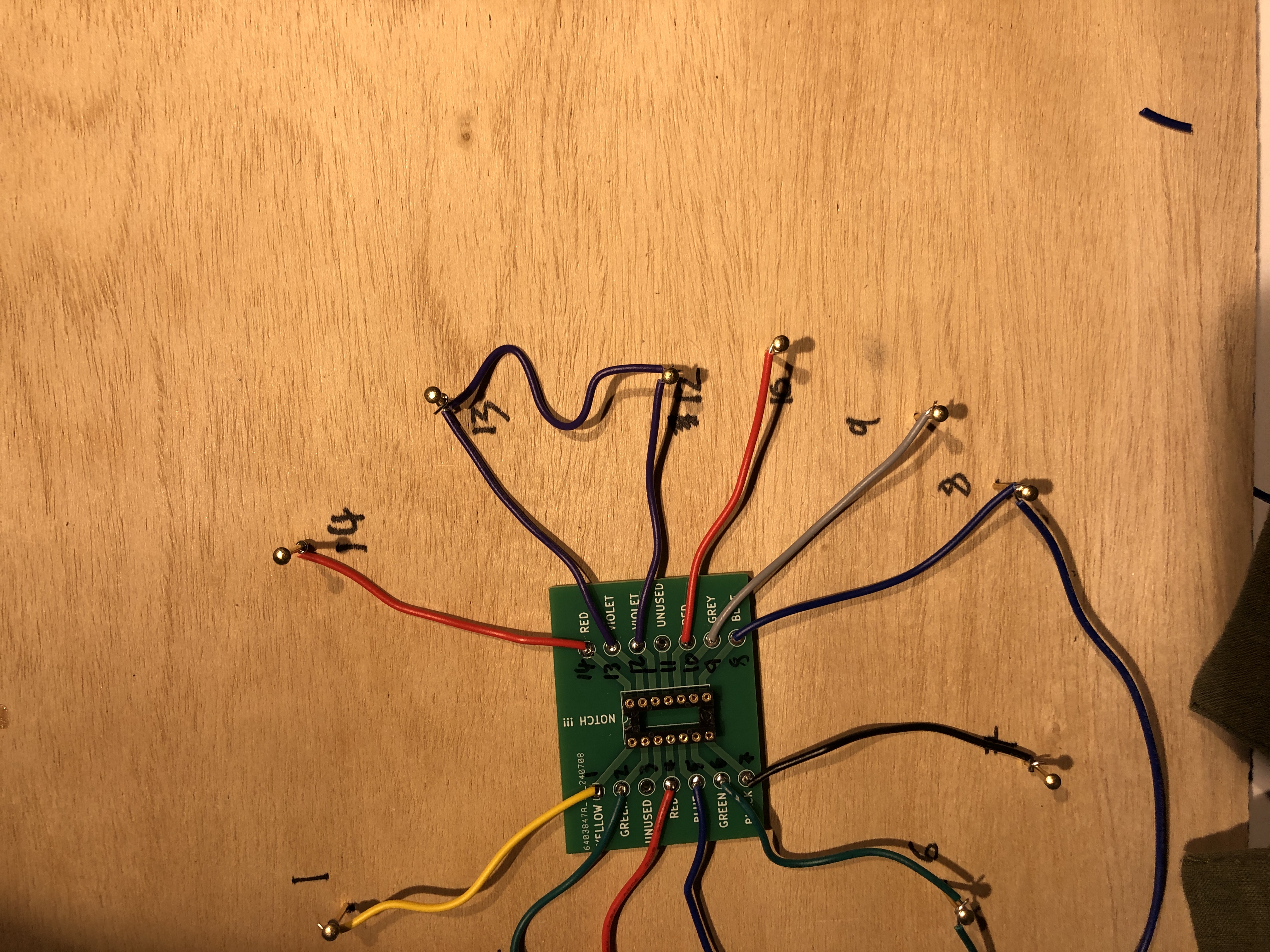
Connect Pins 12 and 13 with a Violet Wire
As always, make sure to use the correct color. As always, don't make the wire too short. It's better to have plenty of extra.
Connect Pins 4, 10, and 14 with a Red Wire
Using red wire, connect pins 4, 10, and 14. You can use an extra nail if you wish, or run the wire from one pin to another.
Pins 4, 10, and 14 are all connected together, forming the +9v node. Once any wire is connected to a node it too becomes equivalent to that node, so the order of the connections don't matter at all.
As always, make sure to use the correct color. As always, don't make the wire too short. It's better to have plenty of extra.
Add Nails and Install the Photoresistors
Add a pair of nails for each photoresistor. Take advantage of the long leads to space the nails out, but put them close enough that you can wrap each lead 1-3 times around their respective nail
Once you have added the nails, add the photoresistors by wrapping each lead around its respective nail. Make sure that the leads don't touch each other as that would cause a short circuit. Make sure that the photoresistor faces up so that it will detect your hand.
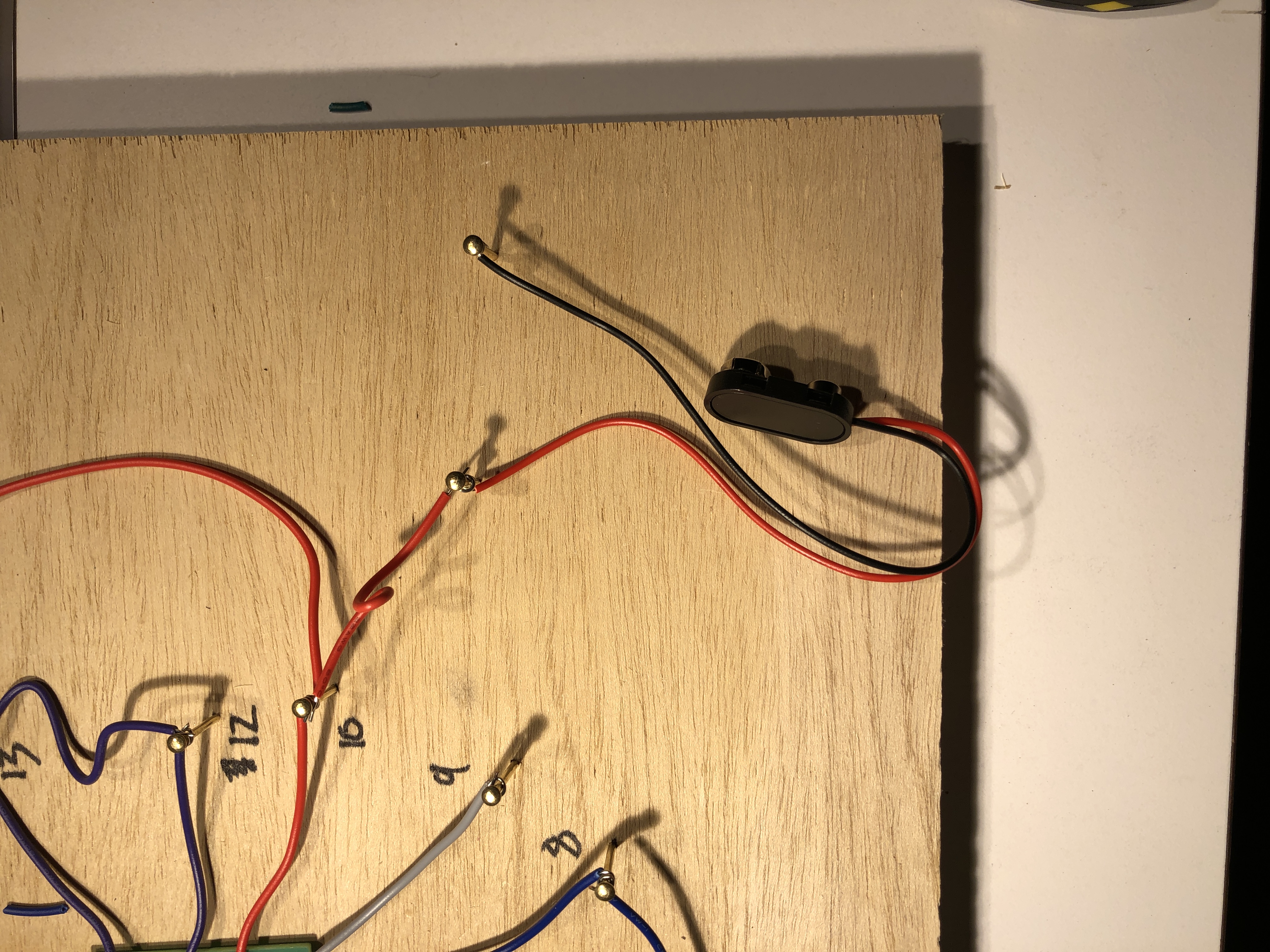
Add Nails for the Battery Connector
Add two nails for the battery connector.
Note that the positive (red) wire of the battery connector will eventually connect with pins 4, 10, and 14, so if you choose to mount your battery near to one of these pins you can connect the positive (red) wire of the battery connector directly to any of those pins.
Similarly, the negative (black) wire of the battery connector will eventually connect to pin 7, so if your battery connector is near pin 7 you can connect the positive (black) wire of the battery connector directly to that pin.
If the battery is close to neither connector, add a pair of nails for the battery connector near the battery connector. Using a red wire, connect the positive (red) wire of the battery connector to any of pins 4, 10, or 14.
The wires of the battery connector may already be stripped, but they may be stripped only a tiny bit. Strip them longer, around half an inch, so that they can be wrapped around the nail a few times. Strip carefully as these wires are often very thin and tear easily.
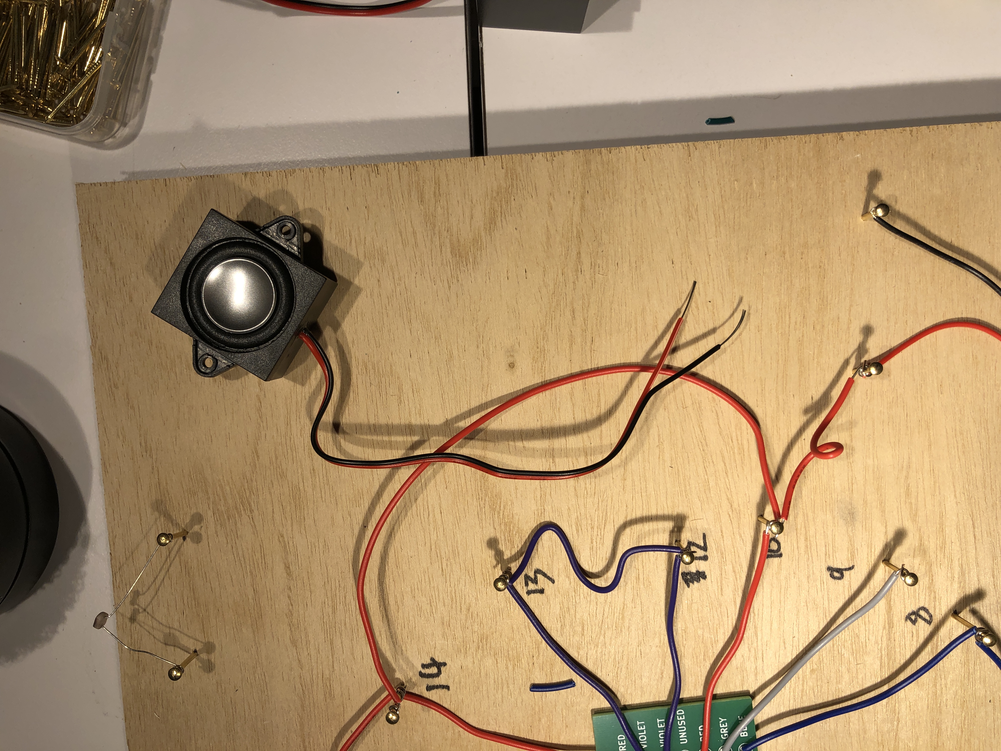
Mounting the Loud Speaker
The wires of the loudspeaker may already be stripped, but they may be stripped only a tiny bit. Strip them longer, around half an inch, so that they can be wrapped around the nail a few times. Strip carefully as these wires are often very thin and tear easily.
Decide where you want to mount the loudspeaker. Use double-sided tape to mount the speaker to the board.
Add Nails for the Loud Speaker
Add a pair of nails for the loudspeaker. As with the battery connector, Note that the positive (red) wire of the speaker will eventually connect to the +9V node (which is pins 4, 10, and 14, and the battery positive (red) wire so if your speaker is near to any of those you can connect the positive (red) wire of the speaker directly to any of those pins.
The black wire of the loud speaker will need its own nail.
Wrap the stripped ends of the loudspeaker wires around their respective nails
Important: Note that the black wire of the speaker does not connect to pin 7, even though it is black. This is the only wire that breaks the color assignments
Connect the Red Wire of the Loud Speaker to the +9V node
If the red wire of the loud speaker was not close enough to be wired directly to any of pins 4, 10, and 14, or to the battery positive (red) wire, use a red wire to connect the positive (red) wire of the speaker to any of those pins.
Wrap the stripped ends of the loudspeaker wires around their respective nails
Important: Note that the black wire of the speaker does not connect to pin 7, even though it is black. This is the only wire that breaks the color assignments
One Red Wire to Each Photoresistor
One lead of each photoresistor is connected to the red +9V node. Remember that any wire of a node is electrically equivalent, so it doesn't matter if you connect it to pin 4, 10, 14, the red wire from the speaker, or the red wire of the battery connector. They are all equivalent. You can choose the one that is closest or most convenient, or you can be creative and connect it to one that is further away in some interesting manner.
Make sure to use a red wire!
Photoresistors are unpolarized so it doesn't matter which lead you choose.
Pin 1 to one Photoresistor
Add a yellow wire from pin 1 to one of the photoresistors. One lead of the photoresistor is already connected via a red wire to +9V, so this yellow wire will attach to the other lead of the photoresistor.
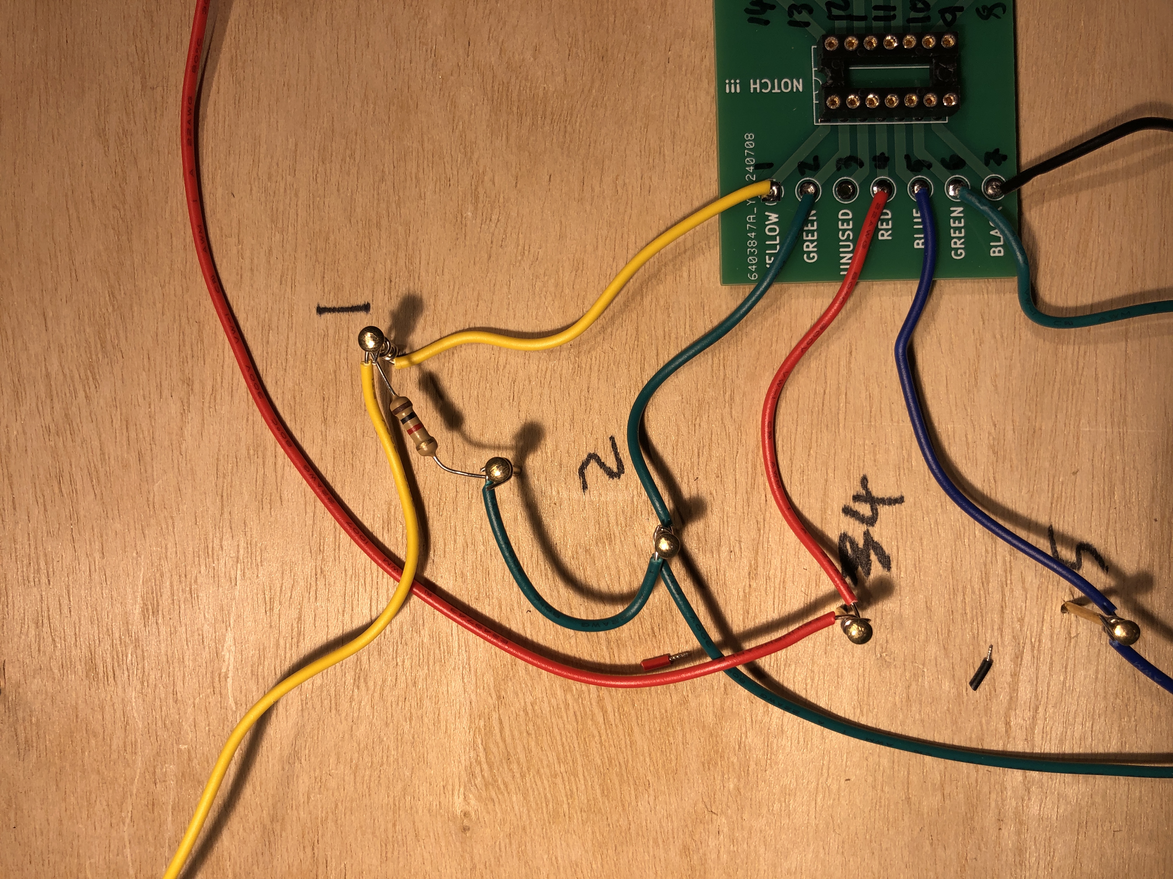
1K resistor between Pin 1 and Pin 2
Wrap the leads of a 1K resistor between pin 1 and pin 2. If pins 1 and 2 are too far, use another nail, and then connect that nail to the appropriate pin using the correct color wire.
Add Black Wire from Pin 7 to Battery Negative
The negative end of the battery (black wire) is the ground node. Pin 7 needs to connect to this node, so run a black wire from pin 7 to the negative end of the battery (black wire). As always, make this wire a little longer than necessary.
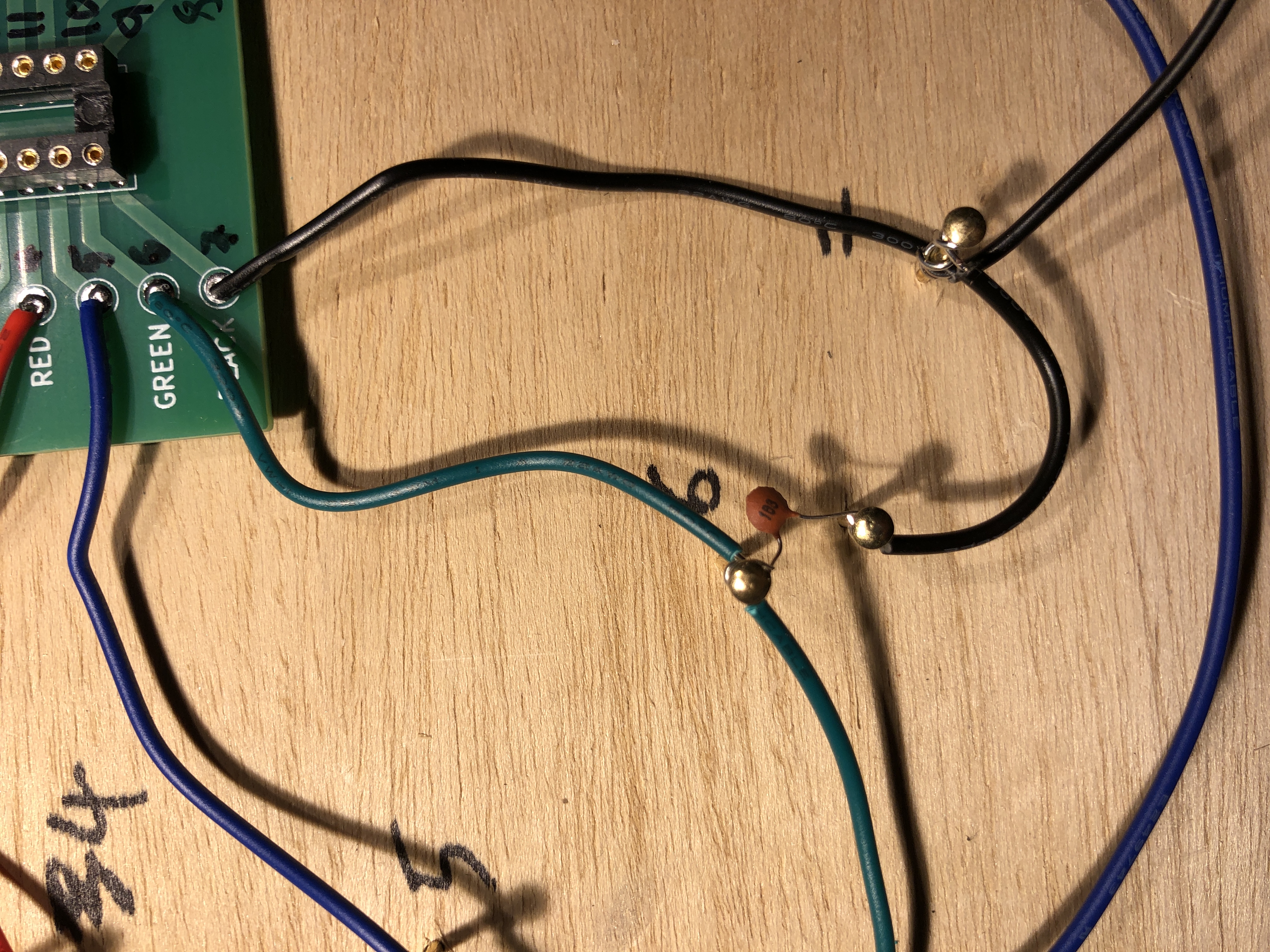
Add the 0.01 Microfarad Capacitor
Locate the 0.01 microfarad disc capacitor. The marking on the disc capacitor should read "103". Be very careful not to confuse this with the other disc capacitor. This capacitor is installed between pins 6 and 7. Note that this capacitor has very short leads, and they may be too short to span the distance between pins 6 and 7, so use an extra nail if you have to.
Wrap the leads of the 0.01 microfarad disc capacitor at least once around the nails. This disc capacitor is unpolarized so it doesn't matter which end is connected to which pin.
If you used an extra nail, connect the extra nail to wherever it needs to go with the correct wire (green if it goes to pins 6, black if it goes to pin 7).
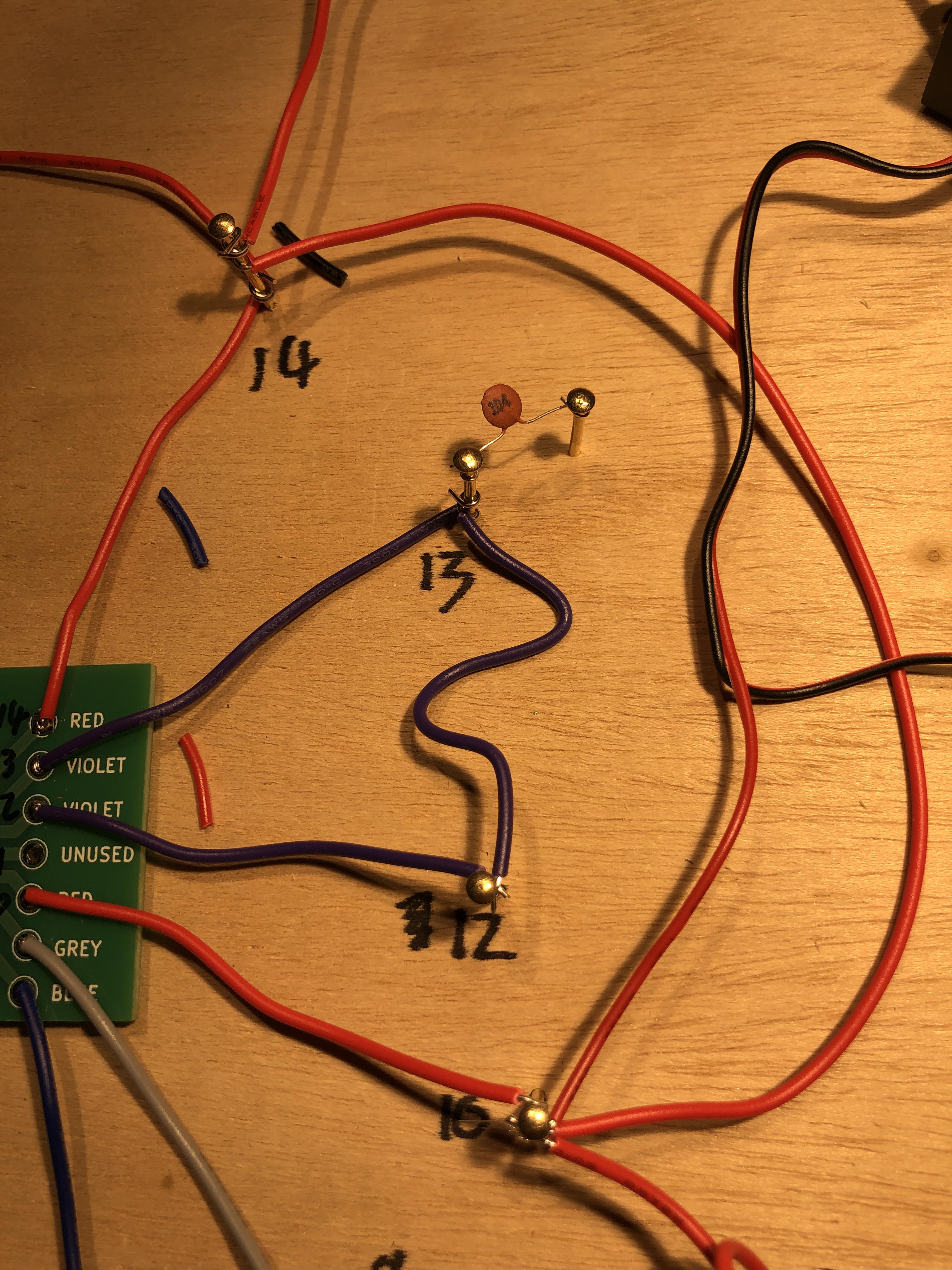
Add the 0.1 Microfarad Capacitor
Locate the 0.1 microfarad disc capacitor. The marking on the disc capacitor should read "104". Be very careful not to confuse this with the other disc capacitor. One end of this capacitor connects to pin 12 (or 13), and the other end to the ground node. Note that this capacitor has very short leads. Add a nail near pin 12 (or 13). This disc capacitor is unpolarized so it doesn't matter which end is connected to which pin.
Wrap the leads of the 0.1 microfarad disc capacitor at least once around the nails.
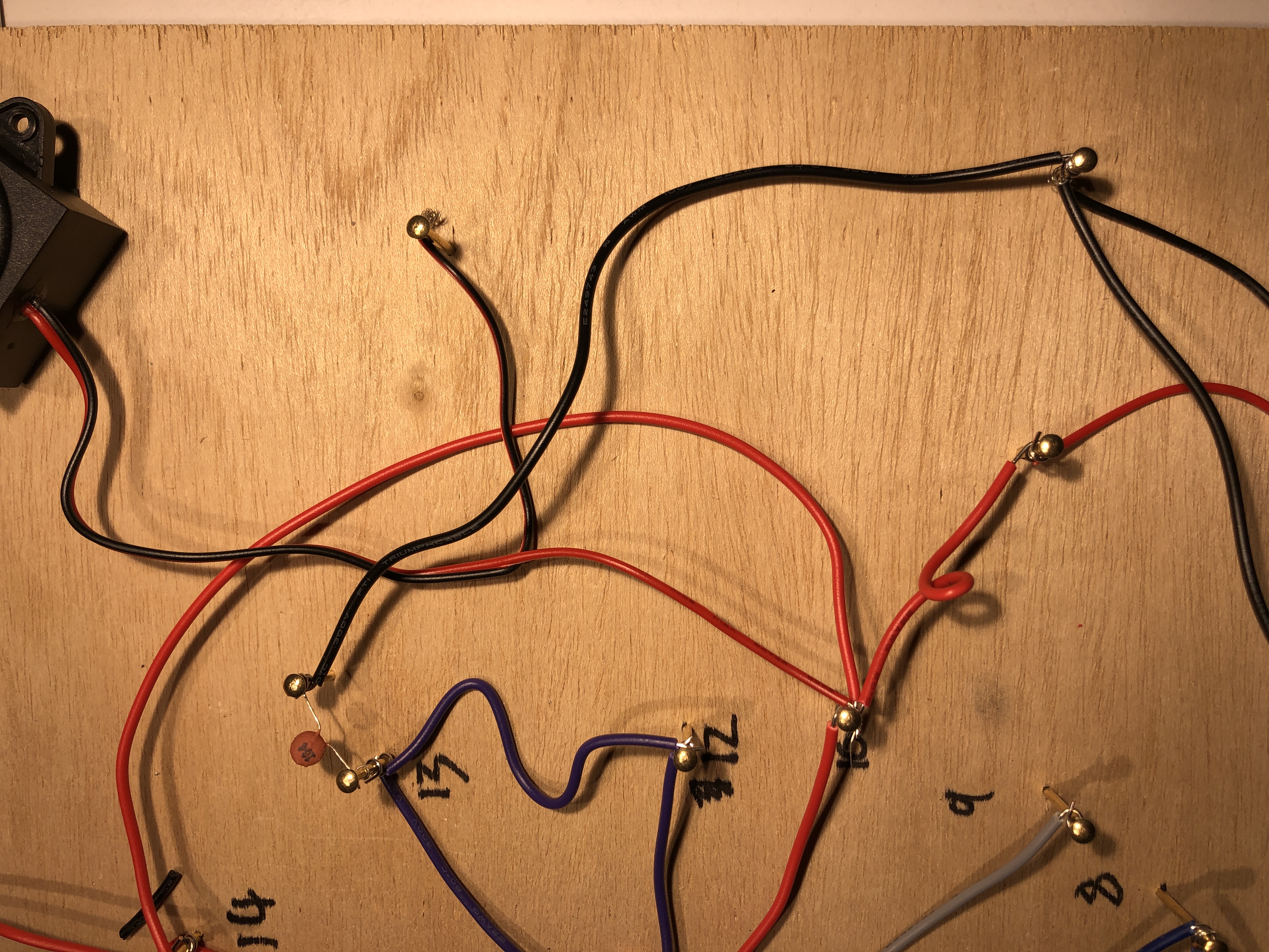
0.1 Microfarad Capacitor to Ground
The other end of the 0.1 microfarad disc capacitor goes to the ground node, so using a black wire connect the unused end of the 0.1 microfarad disc capacitor to any of the ground node connections, such as the negative (black) wire of the battery.
Other End of Other Photoresistor to Pins 12 and 13
One of the photoresistors has one lead that is not connected to anything else. This needs to be connected to either pin 12 or 13 using a violet wire.
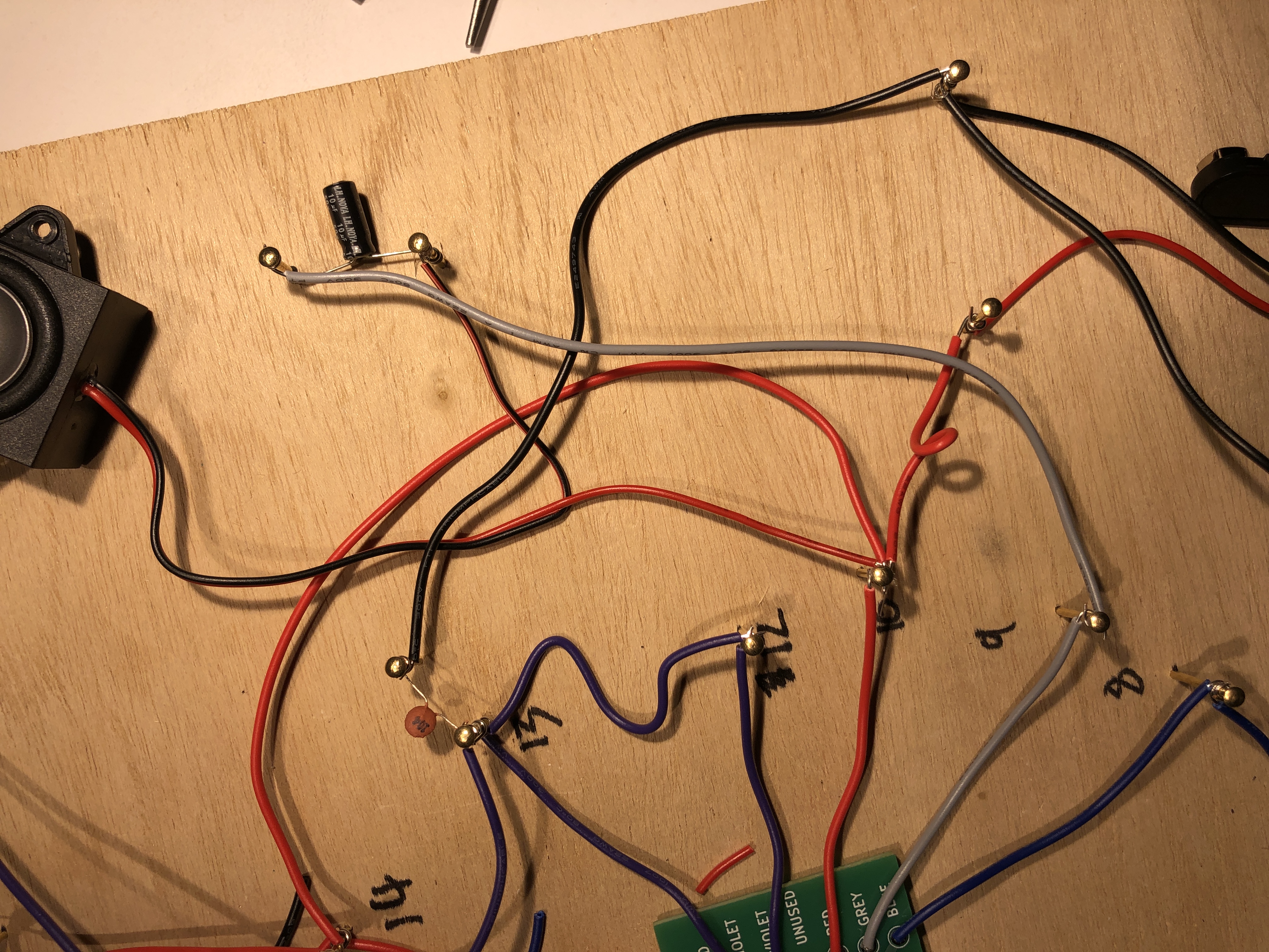
10 Microfarad Electrolytic Capacitor to Loud Speaker
Add a new nail about 1" away from the loud speaker black wire.
Locate the 10 microfarad electrolytic capacitor. Important: This capacitor is polarized meaning that it must be connected in the proper orientation. The longer lead is the positive end, and it must be connected to the loud speaker black wire.
Spread out the two leads of the 10 microfarad capacitor. Wrap the longer lead around the loud speaker black wire nail. Wrap the shorter lead around the new nail.
Using a grey wire, connect the shorter lead of the 10 microfarad capacitor to pin 9.
Double Check Your Work
In the next step you will solder all of your connections. While not irreversable, it is inconvenient to change connections once soldered, so it is best to double check that your wiring is correct before proceeding.
The best way to do this is to ask your neighbor to check your circuit while you check theirs. Don't explain your circuit to your neighbor: let them work it out themselves.
Soldering
- Gently wipe the iron clean, and then apply some fresh solder
- Hold the soldering iron stationary against the wires to be soldered. Do not move it.
- Feed some solder directly onto the iron, and when it melts draw it onto the wires.
- Move the solder, not the soldering iron
- When you are done, do not wipe the soldering iron. The solder on it protects the tip.
Insert the 567 Dual Timer Integrated Circuit
Insert the 567 Dual Timer Integrated Circuit (IC) into the socket. Note that that there is a notch at one end.
The pins on the IC are intentionally a little bit wider than the holes in the IC socket. Hold the IC sideways and press one row of pins against the table to bend them in a little bit. Compare to the holes on the IC socket to see how much.
Insert the IC so that the notch lines up with the notch on the green board.
Battery
Plug in the 9V battery. Make sure the battery is in the right orientation before plugging it in.
References
- Making Music with an Atari Punk Console article by Forrest M. Mims III on the Jameco website, based on his original circuit from the Radio Shack Engineer's Mini-Notebook series
- Forrest M. Mims III Engineer's Mini-Notebook on 555 Timer IC Circuits published by Radio Shack